MCGLYNN
CONSULTANCY
SERVICES LTD
Manufacture
MCC and ICA Section Manufacture
McGlynn Consultancy can work from a P&ID and a Single Line diagram or a Load Schedule, in order to produce a conceptual MCC Layout.
The client's available footprint need not be excluded since MCC and ICA manufacture can be both separate or combined, but does not necessarily, need to be within a linear design
McGlynn Consultancy can attend site and survey existing equipment to be controlled by the new MCC / ICA in addition to that which is new equipment, and needs to be accommodated by the new MCC
MCC/ICA manufacture requires a good deal of system documentation.
In order to target MCC/ICA FAT Test status, MCS can work with the following documentation and schedules:
-
P & ID's
-
URS / FDS
-
Single Line Diagram
-
Block Cable Diagram
-
Load Schedule
-
Instrumentation Schedule
-
Actuated Valve Schedule
-
Solenoid Valve Schedule
-
Equipment Schedule
-
DSEAR Equipment Schedule
-
Package Plant Signal Schedule
-
I/O Schedule
-
Telemetry Schedule
From the above documentation, MCS can provide:
-
An MCC/ICA footprint
-
MCC/ICA Layout
-
Main Surge Protection
-
Neutral/Earth Link
-
MV/LV Intertripping Section
-
Main / Generator Incomer Section
-
Active Filtration Feeder
-
PFCC Feeder
-
Bus Coupling Arrangement
-
Metering Section
-
Common Supplies Section
-
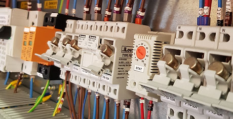
Cubicle Sections
-
VSD/Soft Start Section
-
UPS Section
-
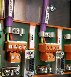
ICA Section comprising all requisite controls
-
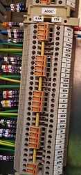
Terminal Chamber(s)
Associated with this degree of supply would be:
-
Drawings and Documentation
-
Schematic Diagrams
-
Power terminal Schedules
-
Terminal Schedules
-
Earthing Detail
-
Common Bonding Detail

.jpg)
.jpg)

MCC and ICA Section Testing and FAT
Testing ahead of FAT testing on a new MCC/ICA Section is rigorous.
Initial testing is visual.
Evidence of the MCC/ICA finished colour scheme is confirmed with a RAL colour chart as provided by the steel work manufacturer. Evidence of the paint depth will be provided
Further practical assessments can be made on all mechanical aspects for example, facia opening/closing, indication systems at a correct height, plinths at designed height, vermin boards fitted (accompanied with any COSHH data sheet), adequate earthing arrangements in each section
On completion, further checks are completed including:
-
Component locations as per previous approved layouts
-
Equipment used is in line with BOM (Bill of Materials)
-
Cable sizes verified
-
Wiring colours as prescribed by purchaser
-
Wiring terminations/crimps are as specified
-
Cable ducting routes comprise adequate spare capacity
-
Point to point wiring testing completed and verified on tick /schematic diagram
At this point a "live" testing scenario is initiated. Equipment under test at this point is confirmed as "demarked and barriered" away from non associated personnel. A people traffic management routing could be in operation
Depending on the system under test, safety circuits are tested first. Temporary links are inserted to simulate "healthy" conditions.
Power is applied and the MCS Test List is consulted.
As a generic test scheme, testing would be as follows:
Power on - verify
Emergency Stops - prime the respective circuit and verify health.
Remove the link - check circuit isolation and indication
Perform similar checks on::
Isolators (with auxillaries)
Pressure Switches
Level Systems
Flow systems
Heating systems
After priming each individual circuit
.jpg)
.jpg)
.jpg)